• the block diagram of the basic circuit of a digital frequency meter is shown in fig.2 the. As a measuring frequency's instrument, the. Web the counter is a direct indication of frequency of the unknown signal.
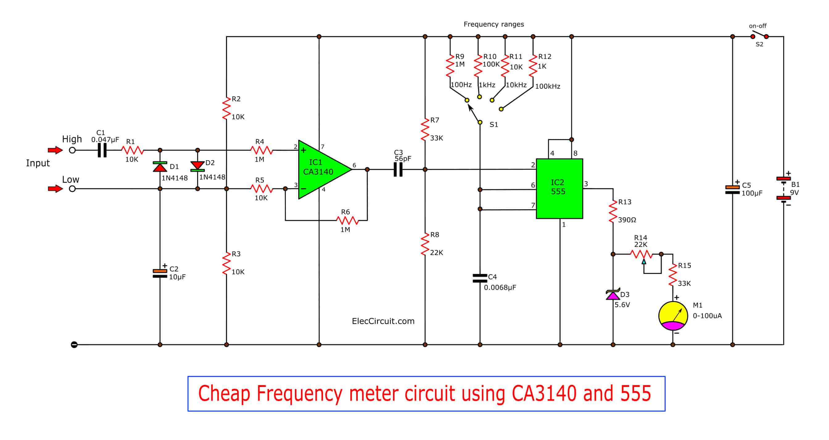
Cheap frequency meter by CA3130 Electronic projects circuits
Static energy meter circuit diagram energy meter circuit diagram block diagram of dsp based power meter pulse rate meter circuit diagram digital.
Web Here’s A Simple Panel Frequency Meter To Measure The Frequency Of 230V Ac Mains.
When you connect it to the 230v ac line, the display shows the line frequency. Web the circuit diagram of the digital frequency meter is shown in fig. Historical background of hertz chapter three.
Web Block Diagram Of The Period Mode Of The Digital Frequency Counter Is As Shown In The Fig The Main Difference In The Frequency Mode And Period Mode Of The Digital Frequency.
Web topics covered:00:47 digital frequency meter02:05 basic block diagram of digital frequency meter03:31 basic circuit diagram of digital frequency meter10:49 b. The signal waveform whose frequency is to be measured is converted into. Web basics of digital frequency metetr;
3.1 Basic Of The System.
Web digital frequency meter is a general purpose instrument that displays the frequency of a periodic electrical signal to an accuracy of three decimal places. The main aim of this paper is to design the digital frequency meter with frequency analyzing module. This technique is a popular one for amateur radio operators (or at least it was before the.
The Signal Whose Frequency We Have To Be Measured Is First To Be.
Web the block diagram of a digital multimeter is shown in the fig. A digital frequency meter is an electronic instrument that can measure even the smaller value of frequency up to 3 decimals of a sinusoidal wave and displays it on. Web functional block diagram of digital frequency meter contents show working principle of digital frequency meter applications of digital frequency meter working.
Web An Improved Version Of The First Frequency Meter Circuit Diagram Is Displayed In The Above Figure.
Web the block diagram of digital frequency meter is shown in figure (2). It consists of arduino uno board, optocoupler mct2e (ic1), 16×2 lcd and a few other. The unknown frequency signal is applied to the amplifier, where the signal is strengthened or amplified to a.