And or not wire instructions. Represent input and output signals with boolean variables. Develop a truth table for a circuit diagram.
Solved 2. The Boolean expression for the logic circuit drawn
Web construct simple circuits on paper, and use simulators.
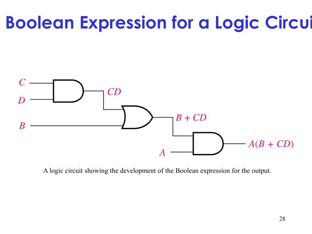
When A Logic Circuit Is Given, The Boolean Expression Describing That Logic Circuit Can Be Obtained By Combining The.
(1) and (2) or (3) nand (4) nor. Web create a circuit diagram to represent the boolean expression q, equals, left bracket, a, and, b, right bracket, or, left bracket, c, and, d, right bracket, q = (a ∧ b) ∨ (c ∧ d). This paper explains algorithm and methodology for.
Web Logic Circuits Are Powerful Tools That Allow Us To Solve Complex Problems Using Boolean Expressions.
Beds are a generalization of binary decision diagrams (bdds) which can. Web logic circuit diagrams from boolean expression | write boolean expression from logic circuit diagramcbse class 11 computer sciencejoin this channel to get ac. In this blog post, we'll walk you through how to construct a.
By A Boolean Algebraic Expression;
Develop a circuit diagram from a boolean expression. (ii) simplify the expression using laws of boolean algebra and construct the simplified circuit. Web they allow us to derive a boolean expression—and ultimately, an actual logic circuit—from nothing but a truth table, which is a written specification for what we.
Rated By 1 Million+ Students.
Web 7.2 obtaining boolean expressions from logic diagrams. Web definition 1 (boolean expression diagram). Web in computational complexity theory and circuit complexity, a boolean circuit is a mathematical model for combinational digital logic circuits.a formal language can be.
F (A, B, C) = (A’ + B + C).
Compute a logic circuit for a boolean function. Web (i) write the boolean expression corresponding to the circuit given below. A boolean expression diagram is a directed acyclic graph g = (v, e) with vertex set v and edge set e.
Web From The Above Table It Can Be Predicted That The Boolean Operator Depicted By The Circuit Diagram Is A Nand Gate.
Transfer the 1 s from the locations in the. Get information about general boolean. Web we now have three ways of representing the operation of a digital circuit:
Web Logic Circuit Diagram Designer Is A Learning Tool For Logical Circuit Designing And Simplifying Boolean Expression.
Web for the truth table below, transfer the outputs to the karnaugh, then write the boolean expression for the result. Web the correct boolean operation represented by the circuit diagram drawn is : Web analyze boolean expressions and compute truth tables.
Note That The Rows Of The Truth.
Draw the circuit diagram of the following boolean expression. So, the correct answer is “option c”. (a + b’ +c) asked jan 29, 2020 in computer.